
|
 |
 |
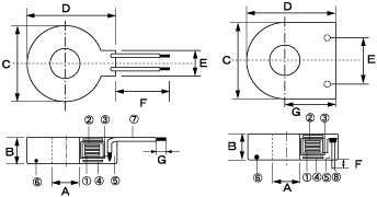
ZCT STANDARD DIMENSION |
| |
| MODEL NO. |
A(Min.) |
B(Max.) |
C(Max.) |
D(Max.) |
E |
F |
G |
RATED CURRENT |
| SH7SP |
6.8 |
6.0 |
17.0 |
18.0 |
10 |
3.0 |
丂 |
FOR 30A |
| SH7P |
6.8 |
7.0 |
17.0 |
18.0 |
10 |
2.5 |
丂 |
乂 |
| SH7 |
6.8 |
7.5 |
17.0 |
19.5 |
6.0 |
70.0 |
3.0 |
30,50A |
| SH9 |
9.0 |
7.6 |
22.0 |
25.0 |
6.0 |
70.0 |
3.0 |
30,50A |
| SH10 |
9.4 |
7.6 |
19.0 |
21.0 |
6.0 |
70.0 |
3.0 |
50,100A |
| SH11 |
10.2 |
9.0 |
24.0 |
27.0 |
6.0 |
70.0 |
3.0 |
乂 |
| SH12 |
10.3 |
8.7 |
22.0 |
24.0 |
6.0 |
70.0 |
3.0 |
乂 |
| SH15 |
13.6 |
9.3 |
28.3 |
31.0 |
6.8 |
70.0 |
3.0 |
100,125A |
| SH16 |
15.5 |
9.0 |
30.0 |
33.0 |
6.0 |
70.0 |
3.0 |
100,125A |
|
|
|
MATERIALS |
| |
| No. |
NAME |
MATERIALS |
| 1 |
Core |
Permalloy |
| 2 |
Core case |
僫僀儘儞丂P.P resin |
| 3 |
Winding |
2UEW 冇0.08-1.0 |
| 4 |
Shiled
Plate |
Iron |
|
| No. |
NAME |
MATERIALS |
| 5 |
Encapsulati |
Epoxy resin |
| 6 |
Outer case |
UL-94 V-O丂乮擄擱惈乯 |
| 7 |
Lead Wire |
Tinned Cu PVC coat |
| 8 |
Lead
pin |
Tinned
Cu 冇08 |
|
|
|
PROPERTIES |
| |
| ITEM. |
Propertu |
Condition |
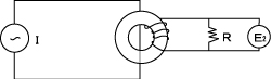
| Output |
E2 : 17-22mV |
I ; 25mA, f ; 60Hz, OR ; 1K兌 |
| Remainence
magnetism |
兠 ; 10% Max. |
IDC : 50A OutPut voltage ratio after
magnetized |
| Thermal
property |
兠冄 ; 亇10% |
-10乣亇50亷 Output voltage ratio |
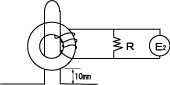
| Permissible
Unbalance |
Eb
; 10mV Max. |
I
; 180A, R ; 1K兌, 60Hz |
|
|
DIAGRAM of PROPERTY TEST |
| |
| 1,Output
(E2) : |
| |
Measured after demagnetization. |
|
|
2,Permissible Unbalance (Eb) : |
| |
Peak effective
value measured by turning ZCT round the primary einding
jig. |
|
 |
 |
|
|
|

